large-range-of-in-situ-testing-rigs
IN SITU TESTING

Ground Investigation is a leading provider of in-situ testing services in New Zealand. We specialise in direct-push testing methods:

    • CPT – Cone Penetration Testing
    • SCPT – Seismic Cone Penetration Testing
    • DMT – Marchetti Dilatometer Testing
    • SDMT – Seismic Dilatometer Testing
    • DPSH – Dynamic Probe Super Heavy
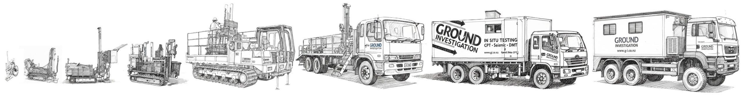
These direct-push techniques are performed using a CPT rig and provide fast, accurate and cost-effective subsurface data with minimal ground disturbance. For these reasons, in situ testing is often replacing conventional borehole drilling in site investigation projects.
Our fleet includes a wide range of CPT testing rigs, from man-portable and small tracked anchored rigs to large ballasted CPT trucks and heavy tracked rigs, allowing us to operate effectively across a wide range of ground conditions and site constraints.
We provide nationwide coverage, with our North Island base in Auckland and South Island branches in Christchurch and Dunedin. We have a team of highly experienced CPT operators and engineers with specific in situ testing expertise.
See some of the sites we have tested on with difficult access >>

Cone Penetration Test (CPT)

CPT testing is undertaken by pushing an instrumented cone into the ground at a continuous rate using a CPT rig. A cable from the cone, that runs through the push rods, sends information to a computer at the surface. The cone provides near-continuous data on the properties of the ground as it is pushed in. The cone records cone resistance, qc, sleeve friction, fs and pore water pressure, u2 at 10 mm depth intervals.

At Ground Investigation, we provide a range of different CPT cone sizes and sensitivities and a variety of CPT rigs so that we can meet the requirements of the site, the project, and the ground conditions. Our cones are regularly calibrated in-house in our calibration laboratory in Auckland.
We have some of the most experienced CPT operators in the world, along with recognised industry-leading technical experts with more than 100 years combined experience with CPT operation, data processing and analysis.
CPT testing is undertaken to ISO 22476-1 and CETANZ TG6.

Seismic Cone Penetration Test (SCPT)

A SCPT test is a combination of a standard CPT test and a direct-push downhole seismic test (DPDH). Combined together, the shear wave velocity (VS) resulting from the downhole seismic tests can be obtained in addition to the usual CPT results (qc, fs and u2).

At Ground Investigation, we perform this combination of tests by pushing a conventional CPT test first and then, usually down the same hole, push a Marchetti true-interval seismic module to obtain the VS measurements. All using the same CPT rig on the same setup.

SCPT testing is a great way to obtain accurate VS measurements in a fast, cost-effective manner along with the benefits of CPT testing. The results of the CPT can also be correlated to VS and, therefore, provide a means of comparing and sanity-checking the measured VS results.
Click here for more information on direct push seismic testing.

Flat Dilatometer Test (DMT) and Medusa DMT

The DMT test is undertaken by direct-pushing a blade into the ground with a CPT rig. At each test depth, a circular steel membrane located on one side of the blade is expanded horizontally against the soil. The pressure readings are recorded at specific moments during the membrane expansion. The blade is then advanced to the next test depth, typically with 0.20 m depth intervals.

At Ground Investigation Ltd, we can undertake this test using the original gas-operated equipment or using the advanced Medusa DMT, which uses an automated oil-pressure system using a motorised syringe.

As the test measures pressures over a known displacement, modulus values are obtained directly. These are correlated to values of Young’s Modulus, E and constrained modulus, M. The test is therefore ideal for settlement and deformation problems.The test is performed in the horizontal direction and so is also excellent for determining at rest horizontal stress ratio, Ko, and for lateral loading problems. Established empirical correlations also exist for reliable estimation of other soil parameters, such as undrained shear strength and angle of friction.

Ground Investigation Ltd introduced this equipment to New Zealand in 2009 and was the first contractor in New Zealand to provide this test. As such, we have over 15 years’ experience with this equipment having done thousands of individual DMT tests throughout New Zealand.

We undertake the DMT work in general accordance with ASTM D6635-01.

Seismic Dilatometer Test (SDMT) and Seismic Medusa DMT

A SDMT test is a combination of a standard DMT test and a direct-push downhole seismic test (DPDH). Combined together, the shear wave velocity (VS) resulting from the downhole seismic test can be obtained in addition to the usual DMT results.

At Ground Investigation, we perform this combination of tests by pushing a Marchetti true-interval seismic module with a DMT blade attached, so that both tests are done in the same push. We also have a seismic Medusa DMT, which combines the advanced features of the Medusa DMT with downhole seismic testing.

SDMT testing is a great way to obtain accurate VS measurements in a cost-effective manner along with the benefits of DMT testing. The combination allows for modulus estimates at very low strains and at typical operational strains so as to better understand the modulus/strain behaviour of the soil.
Click here for more information on direct push seismic testing.

Dynamic Probe Super Heavy (DPSH)

The dynamic probe test involves driving a solid 90o cone on the end of a rod string into the ground using a drop hammer and counting the number of blows per 100 mm.

DPSH uses a hammer with the same weight and drop height as the Standard Penetration Test (SPT) and the same size diameter cone (50 mm). In effect, this test is like a continuous SPT test. This has the advantage that it doesn’t ‘miss’ information over the depth intervals between the tests as the SPT does and a borehole isn’t required.

Torque readings can be taken as the test is progressed to provide a measure of skin friction on the rods. This allows a correction to be made so that the blow count relating only to the cone resistance can be estimated.

It is a relatively crude test and the results provide an indication of the ground conditions rather than providing soil parameters that can be relied on for design purposes. It is a good test for estimating the depth to a rock surface or for providing rough ground profiling to help establish harder and softer layers.
At Ground Investigation Ltd our small tracked Pagani CPT rigs are set up to do DPSH testing, as well as CPT testing. In this way, a combination of CPT and DPSH can be undertaken
The testing is undertaken in general accordance with ISO 22476-2 Dynamic Probing.
GEOPHYSICS

Ground Investigation Ltd provides a focused range of geophysical methods tailored specifically to geotechnical applications.

We specialise in non-intrusive and minimally intrusive techniques that are both cost-effective and designed to minimise site disturbance.

Our core capability is seismic testing, used to determine key parameters such as shear wave velocity (Vs), time-averaged shear wave velocity over the upper 30 m (Vs30), and site period (T₀). Most methods also allow for 1 D or 2 D ground profiling.

Our current geophysical services include:

  • DPDH – Direct Push Downhole Testing
  • DPCH – Direct Push Crosshole Testing
  • MASW – Multichannel Analysis of Surface Waves
  • MAM – Microtremor Array Measurement
  • HVSR – Horizontal to Vertical Spectral Ratio
  • SRT – Seismic Refraction Tomography
  • ERT – Electrical Resistivity Tomography
  • Magnetometer Surveys

Ground Investigation Ltd has a team of highly experienced and qualified geophysicists with specialist expertise across these methods. Seismic geophysical testing has been a core part of our service offering since 2010, reflecting our long-standing commitment to technical excellence and innovation in site characterisation.

Direct Push Downhole Seismic Test (DPDH)

The direct push downhole test (DPDH) is a direct seismic measurement technique used to determine the shear wave velocities (VS) of soil and weak rock materials.  This is similar to downhole tests done in boreholes, except the seismic module is directly pushed into the ground using a CPT rig.  It is often done in conjunction with CPT (then called SCPT), or with DMT (SDMT).

At Ground Investigation, we use the Marchetti true -interval seismic module, which contains two receivers (geophones) spaced 500 mm apart. When a shear wave generated at the surface reaches the module, the upper receiver detects the wave first and the lower receiver detects it shortly afterward. The time difference between these arrivals is determined using cross-correlation processing, and VS is calculated from the known receiver spacing and travel time.
This true-interval configuration avoids errors associated with “pseudo-interval” systems that rely on a single receiver and an assumed surface trigger time. By measuring travel time directly between two receivers at depth, the method improves accuracy and repeatability of VS measurements, typically achieving repeatability on the order of about 1%.
This method is fast and efficient with processing done in real time on site using the acquisition software. Post-processing is done by our experienced geophysicists ensuring that the results provided to our clients are correct. In our opinion, this is the most cost-effective way of obtaining reliable shear wave velocity profiles.
Ground Investigation Ltd was the first company to introduce this equipment to New Zealand in 2009, and we have had over 15 years of experience with its use and interpretation.
The test is carried out in general accordance with ASTM D 7400M-19.

Direct Push Cross-hole Testing (DPCH)

The direct push cross-hole seismic test (DPCH) is conducted by vertically pushing two separate seismic probes into the ground at a set horizontal distance apart.

This is a direct-push technique, so no boreholes are required. CPT rigs are used to push the probes, so two rigs are generally required to do this test.

Typically, the horizontal spacing between the probes is 1.5 m to 2.0 m and the tests are conducted at depth intervals of around 500 mm.

Each probe has a set of triaxial geophones for measuring primary (pressure) waves and shear waves. One probe acts as the source and the other as the receiver. The seismic wave is generated by hitting the top of the rod string of the source probe. The signal generated travels horizontally and is recorded at the receiver probe. The pressure wave and shear wave velocities can then be determined at each depth increment by picking arrival times in the recorded waveforms. The distance between the probes can be verified from inclinometer readings in the probes.
This method was developed by Brady Cox, Andrew Stolte and Liam Wotherspoon from the University of Texas and the Universities of Auckland and Canterbury. At Ground Investigation Ltd we work in association with Andrew and Laim when carrying out these tests.
The DPCH tests are suited for near surface soils and are particularly useful in ground improvement assessment. Another application for the test is the identification of the depth to fully-saturated soils.

Multi-Channel Analysis of Surface Waves (MASW) and Microtremor Array Method (MAM)

MASW and MAM are complementary surface seismic techniques used together to define a reliable shear wave velocity (VS) profile from near surface to significant depth. MASW uses an active surface source to provide high-resolution stiffness information in the upper ground layers, while MAM uses passive ambient vibrations to extend investigations to much greater depths.

When combined, these methods deliver a continuous, non-invasive stiffness model suitable for seismic site classification (including Vs30), liquefaction assessment, basin depth mapping, and ground response analysis — providing robust subsurface characterisation without drilling.

MASW is carried out using a linear array of geophones laid out on the ground surface. We typically use 24 geophones spaced at between 1 to 3m apart, depending on application.  Seismic waves are generated by hitting a source block set on the ground with a sledge hammer. This creates surface waves (Rayleigh waves) that travel along the ground surface and are recorded by the geophones.
The recorded wavefield is transformed into the frequency–phase velocity domain to produce a dispersion curve. By inversion, the dispersion curve is converted into a 1D sheave wave velocity profile with depth.
MAM uses a 2D array of sensors (geophones/seismometers) usually arranged in an L-shape, circle or triangular pattern. The sensors are left to simultaneously record naturally occurring ambient vibrations. Instead of generating energy with a hammer or weight drop, MAM measures background ground motion produced by wind, traffic, ocean waves, and general environmental noise. Recording durations are typically between 20–60 minutes. An array signal analysis is undertaken on the recorded data which is then transformed into a dispersion curve. The dispersion curve is inverted to produce a 1D shear wave velocity (Vs) profile with depth, in the same way as MASW.
It should be noted that, in most cases, MASW can only reliably estimate to around 15m to 20m depth and so this method alone cannot reliably determine VS30. MAM can investigate significantly greater depths because ambient noise contains very low frequencies, which can’t easily be generated by active means.  For this reason, we strongly recommend a combination of MASW and MAM wherever possible if the aim is VS30.

Horizontal to Vertical Spectral Ratio (HVSR)

HVSR is a passive seismic method used to assess site response characteristics by analysing naturally occurring ground vibrations (microtremors). The technique compares the amplitude of horizontal ground motion to vertical motion across a range of frequencies, allowing identification of the site’s fundamental resonance frequency (f0) and site period, (T₀).

HVSR is performed using a single three-component seismometer placed on the ground surface. The sensor records ambient vibrations generated by sources such as wind, traffic, and ocean waves. The sensor is left to record for around 20 to 30 minutes.

The recorded data is processed to produce an HVSR curve (H/V ratio vs frequency). Peaks in this curve indicate resonance frequencies associated with contrasts in subsurface stiffness — typically the boundary between softer soils and underlying stiffer material or rock.
HVSR is a fast, non-intrusive method for reliably determining site period, T0. There is also a recent ANN model available that allows for direct estimation of VS30 from the HVSR data.

Seismic refraction tomography (SRT)

SRT is a surface-based geophysical method used to map subsurface structure by measuring the travel times of seismic waves refracted through the ground. As seismic waves pass through materials of increasing stiffness, their velocity changes, allowing SRT to define layer boundaries and velocity variations with depth.

SRT is performed using a linear array of geophones connected to a seismograph. A seismic source (typically a hammer or weight drop) generates waves that travel through the subsurface and are recorded by the sensors.

Unlike traditional refraction methods, SRT uses multiple shot locations along and beyond the geophone spread to create a dense dataset. This data is processed using tomographic inversion, producing a 2D velocity model that shows how seismic wave velocity varies both laterally and with depth.
SRT is widely used for geotechnical and engineering investigations, including:

  • Mapping depth to rock and rockhead profile
  • Identifying weathering profiles and rippability
  • Delineating soil and rock stratigraphy
  • Detecting weak zones, faults, or buried channels
  • Supporting excavation planning and earthworks design

SRT provides a cost-effective and non-intrusive means of developing a continuous subsurface model and is often used alongside other geophysical and intrusive methods to improve confidence in ground interpretation.

Electrical resistivity tomography (ERT)

ERT is a non-invasive geophysical method used to image subsurface conditions by measuring the electrical resistivity of the ground. Resistivity varies with soil and rock type, moisture content, density, and pore fluid chemistry, making ERT a powerful tool for identifying changes in ground conditions and stratigraphy.

ERT is performed by placing a series of electrodes along the ground surface, typically in a straight line. A controlled electrical current is introduced into the ground through selected electrodes, and the resulting voltage differences are measured at others.
By systematically varying the electrode combinations, a large dataset is collected and processed using inversion techniques to produce a 2D resistivity section (and, in some cases, 3D models). These sections show how resistivity varies with depth and along the survey line, allowing interpretation of subsurface features.
ERT is widely used in geotechnical and environmental investigations for:

  • Mapping soil and rock stratigraphy
  • Identifying depth to rock and weathering profiles
  • Locating groundwater and seepage zones
  • Detecting voids, cavities, or buried objects
  • Assessing contamination plumes and landfill boundaries
  • Supporting slope stability and earthworks investigations

ERT is often used alongside seismic methods to provide complementary information — combining stiffness (seismic) with material and moisture variability (resistivity) for a more complete understanding of subsurface conditions.

Magnetometer

Our magnetometer is a direct-push probe with a triaxial magnetometer sensor that is pushed into the ground with rods using a CPT rig. 

As it is pushed in, the device continuously records the magnetic field strength in three orthogonal directions (X, Y, and Z). As the sensor approaches a metallic object, such as a steel pile or a buried tank, the local magnetic field is distorted. By analysing the direction of this distortion, the distance and orientation of the object relative to the probe can be estimated. This allows for the precise mapping of buried infrastructure that may be otherwise invisible to surface-level geophysics.

We have used our magnetometer to successfully determine the depth of existing steel and reinforced concrete piles.

LABORATORY TESTING

Ground Investigation Ltd operates an IANZ-accredited soil testing laboratory, delivering reliable, high-quality results to support geotechnical design and construction.

We pride ourselves on fast turnaround times and competitive pricing, helping keep your project moving without delay.

Our capabilities include:

  • Water Content
  • Atterberg Limits (Casagrande and Cone Penetration methods)
  • Linear Shrinkage
  • Fines Content
  • Particle Size Distribution (Dry Sieve, Wet Sieve, Hydrometer)
  • Shrink–Swell Index
  • One-Dimensional Consolidation
  • Compaction Testing (Standard and Heavy)
  • Solid Density
  • Presence of Allophane
  • Organic Content
  • Chloride and Sulphate Content
  • Thermal Resistivity

Our laboratory capabilities are continually expanding. If you require testing not listed above, please get in touch — we may be able to assist.

SAMPLING & PIEZOMETERS

At Ground Investigation we have various direct-push or direct-drive sampling and piezometer installation systems that can be done using a CPT rig or small direct-drive rig – no rotary drilling rig required!

These include:

  • Pagani sampler
  • MOSTAP sampler
  • Shelby sampler
  • Terrier environmental sampling
  • Standpipe piezometers
  • Environmental wells

Pagani Push Sampler

The Pagani CPT sampler is a direct-push sampling system that can be used with most of our CPT rigs. The key features of this system are:

  • Continuous core sampling in 1.0 m runs for shallow depths
  • Discrete 1.0 m run sampling at any depth
  • Obtained by direct push or direct percussion drive – no drilling required
  • Sample contained in 1 m long plastic liners (42 mm diameter)
  • Rapid sampling
Please note that this system is primarily intended as a discrete sampling system. i.e. the sampler can go down to a specified depth and a pick up a 1 m long sample at that depth, rather than having to sample all the way down. Although it can be used for continuous sampling, the efficiency of the method reduces with depth. For continuous sampling below 5m, the cost significantly increases.

MOSTAP sampler

The MOSATP sampler is a direct-push sampling system that can be used with our truck mounted or larger tracked CPT rigs. The key features of this system are:

  • Continuous core sampling in 1.0 m runs, or discrete sampling at any depth
  • Obtained by direct push – no drilling required
  • Sample contained in 1 m long plastic liners (65 mm diameter)
  • Rapid discrete sampling
Please note that this system is primarily intended as a discrete sampling system. i.e. the sampler can go down to a specified depth and a pick up a 1 m long sample at that depth, rather than having to sample all the way down. Although it can be used for continuous sampling, the efficiency of the method reduces with depth. For continuous sampling below 5m, the cost significantly increases.

Direct-push Shelby Sampler

The Shelby sampler has a retractable cone that allows it to be pushed to a selected depth with a CPT rig, the cone retracted, and then a thin-walled Shelby tube sample taken. This is an undisturbed sampling system.

  • Direct-push or direct-drive insertion – no borehole drilling is required
  • Variety of Shelby tube sizing: 54 mm, 73 mm and 85 mm; 600 mm long

Please note that the depth to which this method can be used is dependent on ground conditions.

Standpipe Piezometers

We can install piezometers using our direct drive or direct push systems. Rotary drilled borehole are not required.

Using our CPT rigs, we can install standpipe piezometers by pushing casing pipe with a disposable cone on the end. The casing is pushed to the required depth and then slotted pvc pipe covered with filter sock is placed inside the casing. The casing is then removed whilst sand in placed around the piezometer.

Bentonite is used the seal off the piezo from the ground surface and a flush mounted or standup cover can be installed at the ground surface.

Standpipes installed in this way are typically 25 mm or 32 mm in diameter suitable for ground water level monitoring. Piezometers can be installed up to 15 m depth using this method.
If a CPT is also being undertaken, then the piezometer can be installed down the same hole on the same set up with the same rig. This allows the geotechnical information from the CPT to be combined with piezo installation in an efficient and cost-effective manner.

With our Terrier rig, we can install larger diameter, 50 mm environmental wells in cased boreholes of around 100 mm in diameter. This allows the slotted sections to be backfilled with 2 mm quartz sand and then sealed with bentonite to provide the required screen length. The practical depth limit for these wells is 5 m, but deeper installations can sometimes be achieved.

Environmental Sampling

Our Terrier sampling system is well suited to environmental sampling and the installation of environmental wells due to:

  • No drilling fluids and no excess spoil
  • Minimal risk of sample cross-contamination
  • Large core samples (up to 100 mm diameter) contained in plastic liners
  • Concrete surfaces can be cored prior to sampling using the same rig
  • The borehole can be cased
  • 50 mm diameter wells can be installed
  • Minimal site disruption
Our system uses a custom designed trailer mounted Terrier rig, which is fast to setup on site. It is specifically design for environmental sampling, e.g. contaminated land and groundwater sampling.
Please note that this is a shallow sampling system. It is very efficient down to around 5m depth, after which progress is significantly slower.
DIFFICULT ACCESS

Ground Investigation Ltd specialises in delivering in-situ testing solutions in challenging and difficult access environments.

With many years of experience across thousands of complex sites, we have successfully undertaken projects in conditions that demand innovation, adaptability, and technical expertise.

Over time, we have invested in, developed, and modified specialised equipment, giving us a diverse fleet of rigs specifically suited to constrained and hard-to-reach locations. From steep slopes and soft ground to over-water investigations, low headroom basements, confined spaces, and restricted sites within or between buildings, we have the capability to operate where others cannot.

Our combination of experience, ingenuity, and purpose-built equipment ensures we can deliver reliable results, even in the most demanding conditions.
You may be surprised where our rigs can go.
See some of our case studies discussing difficult access >>

Steep Slopes

Our tracked rigs are capable of tracking on slopes of up to 30 degrees, with winch assistance available for even steeper terrain.We have successfully undertaken CPT and DMT testing on slopes of up to 45 degrees.

We have undertaken modifications to our equipment to make them more suitable for operation under these extreme conditions.

Over water

We have extensive experience delivering over-water in-situ testing projects, including operations from floating barges. Our small and mid-sized tracked rigs are well suited to barge-based work, where the combined weight of the rig and barge provides the required reaction force.

In general, CPT testing is not suitable from floating barges, as buoyancy effects and wave action can influence applied loads and depth measurements. For this reason, a jack-up barge is typically required for accurate CPT testing over water.

However, DMT and dynamic probe testing can be successfully carried out from floating barges, as these methods are less sensitive to movement. We have also successfully completed CPT testing from barges at low tide, where the barge is grounded on the seabed and no longer affected by wave or buoyancy effects. We have also carried out CPT testing from jetties.

Soft Ground

Our tracked rigs have low contact pressure and can track over soft ground. Track mats can be used if the ground is very soft.

We have a custom-made platform that is used as a working platform on very soft soils. We have done many projects where the rig has been lowered on to intertidal mud flats at low tide by helicopter or hiab crane for CPT or DMT testing.

Tight Access and Narrow Entrances

Our small tracked CPT rigs are relatively narrow allowing access through tight spaces, such as narrow gaps, around the back of buildings, through gates or through areas with low height restrictions.

The Pagani rigs are 1.2 m wide with the side racks removed. Our smaller mini-rig is around 700 mm wide, making it capable of accessing through standard doorways. With the mast down, these rigs are around 1.5 m high. For even tighter access, we have man portable rigs.

Inside buildings

Ground Investigation Ltd has done many projects inside buildings. Our range of rigs allow us to access and perform tests in almost any situation inside buildings.

For areas inside buildings with tight access or restricted headroom, e.g. basements, our man portable push equipment is ideal. It requires a height of only 1.5m and is only 600mm wide. The base of the rig can be dynabolted onto a concrete slab floor to provide reaction force. The man-portable equipment uses an electrically operated hydraulic pump, which is quiet and produces no fumes.

Hiab and Helicopter Access

Our Pagani rigs weigh around 1.5 tons. This makes these rigs light enough to be easily lifted with a crane or hiab. Handy for getting over obstructions, such as walls or fences. Our smaller mini-rig weighs less than 800 Kg.

With a large hiab truck, these rigs can be lifted out by up to 25m.

These rigs can also be lifted by helicopter to get to areas that would otherwise be inaccessible.

We have a custom-made platform that is used as a working platform on very soft soils. We have done many projects where the rig has been lowered on to intertidal mud flats at low tide by helicopter or hiab crane for CPT or DMT testing.

Keywords:

Liquefaction | Settlement | Vs30 | Plasticity | Piling | Site Period | Ground Water Measuring | Dissipation |

Auckland | Christchurch | Canterbury | Dunedin | Otago | West Auckland | Invercargill | North Island | South Island |